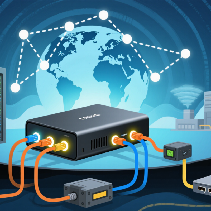
| Primary Function | Copper-to-fiber conversion | Converts electrical Ethernet signals from an RJ45 port into optical signals and converts incoming optical signals back to Ethernet. | Extends a network beyond the normal copper Ethernet limit while preserving Ethernet connectivity. | Use it when an existing copper-based network must connect to a fiber link without replacing all network equipment. |
| Copper Interface Speed | Fast Ethernet | 10/100 Mbps, usually with auto-negotiation and auto-MDI/MDI-X. | Connects legacy 10 or 100 Mbps switches, cameras, access points, or industrial devices to a fiber segment. | Choose this option for older equipment that does not support Gigabit Ethernet. |
| Copper Interface Speed | Gigabit Ethernet | 10/100/1000 Mbps over twisted-pair copper; copper Ethernet is normally limited to 100 meters per segment. | Provides a 1 Gbps copper connection to a fiber uplink or long-distance fiber run. | Choose it for most current office, campus, surveillance, and building-to-building installations. |
| Copper Interface Speed | Multi-Gigabit Ethernet | 2.5, 5, or 10 Gbps may be supported depending on the converter and cabling requirements. | Links high-speed copper equipment to a faster optical network. | Use it only when both connected devices, the cabling, and the converter support the same speed and Ethernet standard. |
| Fiber Mode | Multimode fiber | Common core sizes are 50/125 µm and 62.5/125 µm. Typical short-reach Ethernet links range from a few hundred meters to about 550 meters, depending on the speed and fiber grade. | Transmits optical signals using multiple light paths over relatively short distances. | Choose it for data centers, equipment rooms, and building networks where the fiber distance is short and existing multimode cabling is available. |
| Fiber Mode | Single-mode fiber | Common core size is approximately 9/125 µm. Standard Ethernet optics commonly support distances from several kilometers to 10 kilometers or more, depending on the optic specification. | Transmits light over a narrow optical path with lower dispersion and longer reach. | Choose it for campus links, outdoor routes, telecommunications rooms, and building-to-building connections. |
| Transmission Distance | Short reach | Up to approximately 300–550 meters for many Gigabit multimode applications, depending on the fiber type and optical specification. | Provides a fiber bridge between nearby network cabinets or rooms. | Use it when the link is longer than copper allows but remains within the normal reach of multimode fiber. |
| Transmission Distance | Medium reach | Approximately 1–5 kilometers, commonly using single-mode fiber or a suitable long-reach multimode solution. | Extends Ethernet across large facilities, campuses, or industrial sites. | Choose it after checking the actual fiber length, connector loss, and optical budget. |
| Transmission Distance | Long reach | 10 kilometers is a common Ethernet optical reach; longer distances require equipment and optics specifically rated for them. | Creates a long-distance Ethernet connection over a single-mode fiber route. | Use it for separate buildings, remote surveillance locations, utility sites, and metropolitan links. |
| Ethernet Standard | 100BASE-FX | 100 Mbps fiber Ethernet; reach depends on the fiber mode and optical specification, with multimode links commonly used for short distances. | Connects Fast Ethernet copper equipment to a legacy fiber backbone. | Choose it only when the connected network devices are limited to 100 Mbps. |
| Ethernet Standard | 1000BASE-SX | 1 Gbps over multimode fiber, normally using an 850 nm optical wavelength; reach is commonly up to several hundred meters. | Provides a Gigabit multimode fiber uplink for short-distance networks. | Choose it for data-center or building links with compatible multimode fiber. |
| Ethernet Standard | 1000BASE-LX | 1 Gbps, normally using a 1310 nm optical wavelength; commonly supports up to 10 kilometers over single-mode fiber, subject to the equipment specification. | Provides a long-reach Gigabit fiber uplink. | Choose it for campus or inter-building links where single-mode fiber is installed. |
| Ethernet Standard | 10GBASE-SR | 10 Gbps over multimode fiber; typical reach is up to 300 meters on OM3 and up to 400 meters on OM4 under standard conditions. | Connects a 10 Gigabit copper interface to a short-reach multimode fiber network. | Choose it for high-bandwidth data-center or server-room links. |
| Ethernet Standard | 10GBASE-LR | 10 Gbps over single-mode fiber, commonly rated for up to 10 kilometers using a 1310 nm optical wavelength. | Provides a long-distance 10 Gigabit Ethernet fiber connection. | Choose it for high-speed campus, backbone, and building-to-building links. |
| Fiber Connector | Duplex LC | Small-form-factor connector commonly used with two fibers: one for transmit and one for receive. | Connects the converter to a duplex fiber patch cord or panel. | Choose it when the installed cabling uses LC connectors or when rack density is important. |
| Fiber Connector | SC | Push-pull connector with a larger housing than LC; available for single-mode and multimode applications. | Provides a robust physical connection for common duplex or simplex fiber links. | Choose it when the existing patch panel or fiber cabling uses SC connectors. |
| Fiber Configuration | Duplex fiber | Uses two optical fibers for simultaneous transmission and reception. | Supports standard two-fiber Ethernet communication. | Choose it for the widest compatibility with conventional Ethernet fiber equipment. |
| Fiber Configuration | BiDi or single-fiber | Uses different wavelengths for transmit and receive over one fiber; the two ends must use complementary wavelength directions. | Reduces the number of fibers required for an Ethernet connection. | Choose it when only one usable fiber is available, and verify that both ends are a matched pair. |
| Operating Mode | Unmanaged | Usually plug-and-play, with limited configuration and basic link indicators. | Performs media conversion without requiring an IP address or network management software. | Choose it for simple point-to-point links, small networks, and installations where low maintenance is preferred. |
| Operating Mode | Managed | May support remote monitoring, VLAN settings, link diagnostics, port control, alarms, and network management protocols. | Allows administrators to monitor and troubleshoot the fiber link remotely. | Choose it for enterprise, carrier, industrial, or distributed networks where visibility and centralized control are required. |
| Link Function | Link Fault Pass-Through | Passes a link-down condition from one media segment to the other. | Helps connected switches or devices detect failures across the complete copper-to-fiber path. | Choose it for networks that require faster fault detection and easier troubleshooting. |
| Network Features | VLAN and jumbo-frame support | Support varies by model; jumbo frames may allow Ethernet frames larger than the standard 1,518-byte frame size. | Transports tagged traffic or larger frames without unnecessary packet handling limitations. | Choose these features only when the switches and network architecture require them; verify the supported frame size and VLAN behavior. |
| Power Design | Standard AC or DC power | Designed for office, server-room, or controlled indoor environments. | Supplies electrical power to the converter and its optical and copper interfaces. | Choose it for normal indoor network cabinets and communications rooms. |
| Power Design | Power over Ethernet support | Some converters can pass or provide PoE, commonly for devices such as IP cameras, wireless access points, or VoIP phones. | Combines fiber conversion with power delivery over the copper Ethernet cable. | Choose it when the remote copper device needs power and the converter is explicitly rated for the required PoE standard and wattage. |
| Environmental Rating | Commercial indoor | Intended for clean, temperature-controlled locations such as offices and data centers. | Provides media conversion under normal indoor operating conditions. | Choose it for standard indoor installations without high humidity, vibration, dust, or extreme temperatures. |
| Environmental Rating | Industrial hardened | May support wider temperature ranges, redundant power inputs, stronger enclosures, and improved resistance to vibration or electrical interference. | Maintains fiber connectivity in demanding industrial or outdoor-adjacent environments. | Choose it for factories, traffic systems, substations, outdoor cabinets, and locations with harsh conditions. |
| Optical Compatibility | Optical budget | The available optical power margin must exceed the total loss from fiber length, connectors, splices, and other passive components. | Determines whether the selected converter can reliably transmit over the installed fiber route. | Always check the transmitter power, receiver sensitivity, total link loss, and required safety margin before deployment. |
| Duplex Compatibility | Auto-negotiation and duplex mode | Connected copper devices should agree on speed and full-duplex operation; mismatched settings can cause poor performance or errors. | Coordinates the copper Ethernet link between the converter and the connected switch, camera, or endpoint. | Verify compatibility when connecting older equipment, fixed-speed devices, or equipment with manually configured ports. |
| Best-Fit Scenario | Point-to-point extension | Two converters are installed at opposite ends of a fiber route, with copper Ethernet connected at each end. | Creates a transparent Ethernet link between two separated copper network segments. | Choose this design for connecting two buildings, remote offices, cameras, or network cabinets. |
| Best-Fit Scenario | Fiber backbone connection | One converter connects a copper switch or endpoint to an existing fiber backbone. | Allows copper-only equipment to use the capacity and distance advantages of a fiber infrastructure. | Choose it when replacing the switch is more costly or disruptive than adding a suitable media converter. |